Illustration 1. Projectile Motion
A MECHATRONICS
DEMONSTRATION PROJECT
BY
JOHN LUVERA
MONTVILLE HIGH SCHOOL
MONTVILLE, NEW JERSEY
AND
MICHAEL MCDONNELL
MIDWOOD HIGH SCHOOL
BROOKLYN, NEW YORK
This work was supported by the National Science Foundation under a RET Site Grant 0227479.
The goal of this project was to create a device that would model the physical laws in projectile motion. Using electronic and mechanical devices (mechatronics), a projectile launcher was built. This launcher will be used in a high school physics classroom to demonstrate the laws of projectile motion. When an appropriate angle (20 to 65 degrees) is entered in the software program the basic stamp raises the platform, computes the correct distance for the "catcher" and finally launches the ball towards the target. It was found that the device was consistently accurate for angles from 20 to 30 degrees. When other factors were included in the formula, the accuracy was extended from 20 to 65 degrees. It was discovered that errors in the creation of the device and the limits of the basic stamp were likely to effect the outcome of this experiment.
INTRODUCTION
When objects are thrown or fired from the Earth's surface their trajectory
can easily be determined
by using the laws of physics. These laws govern the distance that a projectile
will travel across the
surface of the Earth. By changing the angle at which a projectile will launch,
one can determine the
maximum distance that it will travel for a given velocity. One military application
of this can be
found in the field of artillery. When the initial velocity can be determined,
it is relatively easy to
determine the correct distance that a shell will travel. These calculations
are typically very accurate
however error does exist. One error that must be taken into account is air resistance
which acts as a
retarding force on the projectile. Another possible error is the Coriolis Effect
that is caused due to
Earth's rotation. This effect is only a serious consideration when a projectile
is in the air for are
extended period of time.
STANDARDS CORRELATION
This project meets the New York State Education Department Physics Standards
in the following way;
Science Standards-Commencement Level
Key Idea 4:
4.1 Energy exists in many forms, and when these forms change energy is conserved.
· describe and explain the exchange among potential energy, kinetic energy,
and internal energy for simple mechanical systems, such as a pendulum, a roller
coaster, a spring, a freely falling object.
· observe and explain energy conversions in real-world situations
Key Idea 5:
5.1 Explain and predict different patterns of motion of objects (e.g., linear
and uniform
circular motion, velocity and acceleration, momentum and inertia).
· sketch the theoretical path of a projectile
5.1f The path of a projectile is the result of the simultaneous effect of
the horizontal and
vertical components of its motion; these components act independently.
5.1g A projectile's time of flight is dependent upon the vertical component of its motion.
5.1h The horizontal displacement of a projectile is dependent upon the horizontal
component
of its motion and its time of flight.
BACKGROUND
Illustration 1. Projectile Motion
Projectile Motion describes the motion of an object, in at least two dimensions,
and experiences that force of gravity in the vertical direction. The motion
of a projectile can be analyzed separately as two independent motions, horizontal
and vertical. A projectile launched at some angle theta and initial velocity
Vo will have a horizontal velocity component of Vocos ? and a vertical velocity
component of Vosin theta.
A projectile's horizontal velocity is constant because it experiences no net
force in the horizontal direction. A projectile's vertical velocity is not constant
as it experiences a net force downward, equal to the weight of the object. This
net force results in an acceleration according to Newton's 2nd law and is equal
to 9.8 m/s2 downward. For the case when the launch height is equal to the landing
height, the time of flight can be found by first finding the time the projectile
takes to reach its maximum height. The vertical velocity of the projectile is
zero at this point and this fact can be used with the equation that describes
the velocity of an accelerated object to find the time.
The time of flight will then be two times the time found above. The time of
flight can now be used with the equation that describes the horizontal displacement
to find the range of the projectile.
EQUIPMENT USED
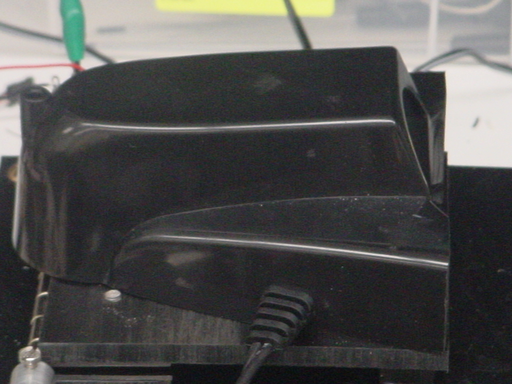
LAUNCHER
The mechanical device used to launch the golf ball is a converted Wilson Putting Pal(shown below).
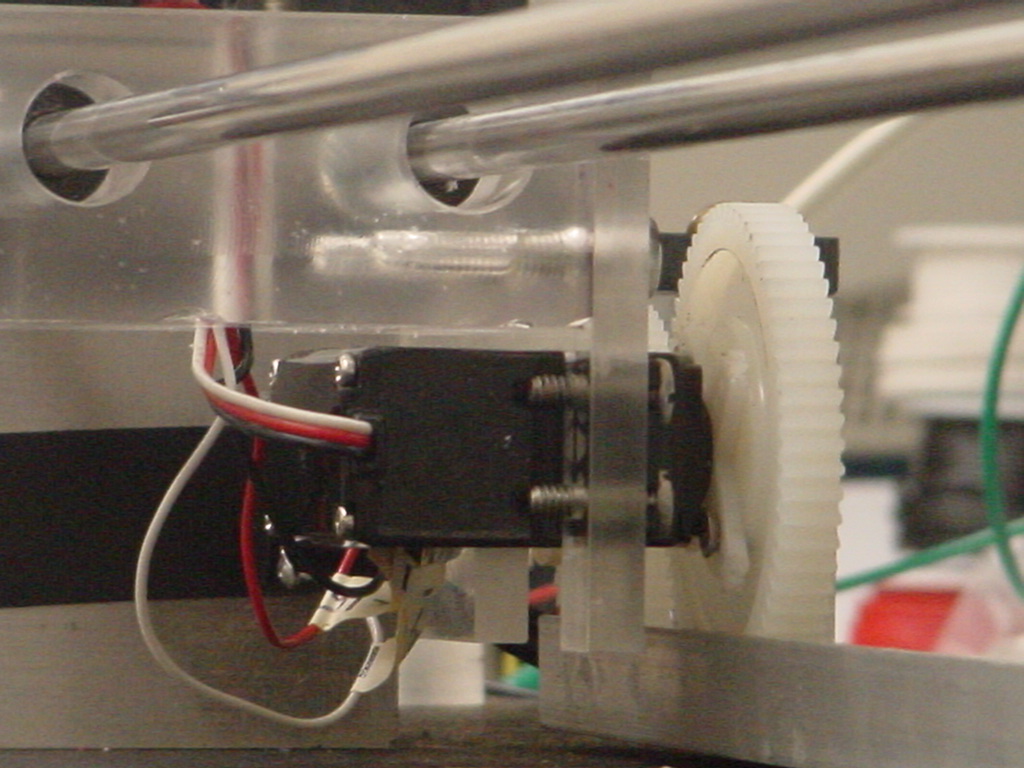
CATCHER
In order to "catch" the golf ball a track was built. The catcher was constructed from a piece of lucite with ball bearings drilled into it. These ball bearings allowed the catcher to move freely along two supporting metal rods. The catcher was driven by a servo motor (shown below), with a gear attached, which was used to move the catcher to a specific point along the track.
EXPERIMENT
Procedure: Verification of Projectile Motion Formula
Goals:
1. Students will relate the angle of release to the maximum horizontal distance
that the projectile travels.
2. Students will identify the angle (450) of maximum horizontal displacement.
Procedure:
1. Connect BS2 to the breadboard by using the DB-15 adapter and to a computer
using a DB-9 serial cable.
2. Download the CatchMeIfYouCan.bs2 file to the BS2
3. At the prompt, the student will enter the desired angle (20-65 degrees) in
the window.
4. The BS2 will elevate the platform to the desired angle, student will be instructed
to place golf ball in launcher.
5. The BS2 will determine the proper distance to move the "catcher"
on the track. The servo motor will move "catcher" to calculated position.
6. Ball will be launched and will land on catcher.
Results:
It was determined that the projectile launcher was accurate for angles from
20 to 30 degrees. When tested at these angles the ball constantly hit the catcher.
However at angles above 30 degrees, the ball was consistently short of the catcher,
which was correctly placed based at the calculated distance.
distance. This effect was more pronounced as the angle increased. We believed
that this effect was due to the position of the golf ball in the launcher. At
high angles, the motor was unable to produce the velocity (3 meters/second),
required to propel the golf ball. We changed the formula so
that the range of the catcher was reduced by the angle of the launcher minus
twenty five. After further testing it was determined that the apparatus was
now accurate between the angles of 20 and 65 degrees.
UNCERTAINTY ANALYSIS
A) Floating Point Calculations
One unavoidable error in this experiment is due to the limitations of the BS2.
The BS2 is unable to make floating point calculations, such as including the
decimal point placement in a calculated number. This means that many calculated
numbers will not be rounded off correctly. It has been determined in this experiment
that this could lead to an error in distance of up to three centimeters. In
order to round numbers off to an acceptable level, another limitation of the
BS2 comes into play. The largest variable that can be stored in the BS2 is a
"word" which has a numerical range of 0-65,535. This indicates that
the highest level of precision in this experiment cannot exceed the thousandth
placement.
B) Initial Velocity of the Golf Ball
In this experiment the initial velocity of the golf ball is assumed to be a
constant. In fact the initial velocity of the ball is highly influenced by the
voltage applied to the solenoid in the launcher. Since the voltage applied to
the solenoid can vary in small amounts, the initial velocity of the golf ball
will have a range of values. Since the velocity of the ball is not being determined
in this experiment, it cannot be used in the formula. In order to account for
this range of velocities, a larger "catcher" has been used. This will
allow for variations in initial velocity.
C) Mechanical Hinge
The hinge that was constructed to open the platform allows for some "play"
in the angle of the platform (see image below). When the platform is raised
to the desired angle, the hinge is unable to hold that angle exactly due to
the mass of the platform, golf ball and launcher. This results in a small drop
in the position of the platform before the golf ball is released.
Full project in .pdf format